In the short time since the February/March 2019 issue of Geosynthetics Magazine was released, I’ve received numerous requests for a response to the article “Changing the ‘one per 500 feet’ paradigm on geomembrane field seam sampling” by Dr. George and Dr. Robert Koerner. Destructive testing is a hotly debated subject in our industry and for good reason. Finding a balance between ensuring quality and turning our liner systems into Swiss Cheese is tough. Appropriate strategies have to take into account the realities of field construction, continuity testing, strength testing, design aspects, potential damage to installed liner, construction cost, construction/permitting timelines and a myriad of other details.
So, a strategy to ensure quality while reducing holes in our liner systems is a very attractive proposition. However, some of the proposals in this article are very disconcerting on many levels and potentially out right dangerous environmentally and financially to site owners.
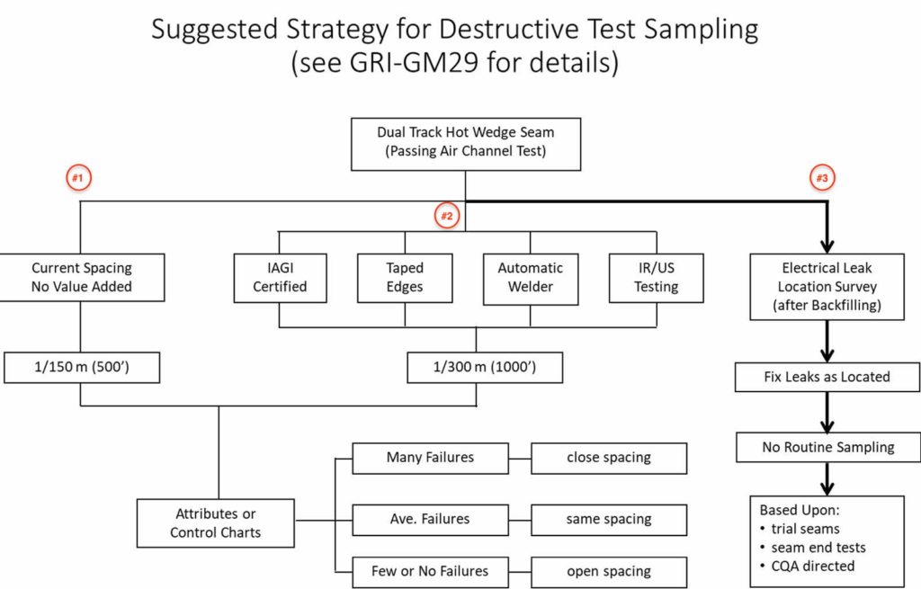
The following image is directly from the article (used with permission) and provides an overview of their three suggested strategies. I have numbered these approaches on the photo for discussion purposes. Approach 3 (seemingly GSI preferred route) is foolhardy while number 2 exposes the owner, engineer, regulator, and community to more risks than needed. Approach 1 is the most reasonable course if some modifications are adopted. I would like to take a detailed look at various aspects of these approaches and their underlying logic to better illustrate the core issues with the methodology presented in their article.
Approach 3
I started with this approach because it is truly the most frightening of the methods. It takes an apples vs cabbages type approach. Air tests help determine the continuity of a seam. A destruct test tells us the “integrity” of the seam’s strength and how that seam might function under load/stress. An Electrical Leak Location Survey (ELLS) tells where holes are located at the moment the test is being conducted. ELLS are important tools and I believe they should be utilized on a regular basis but we need to clearly understand the service they provided to our systems. All three of these testing methods are very important yet each has very different functions and one cannot be substituted for the other.
- Process Precursor: the article states that passing air tests of the dual-track fusion weld are obtained, meaning the seams must pass a continuity test before this method is adopted. This is a good starting point but it does not address the core function of destructive testing which is seam strength.
- The flow diagram is a bit misleading from the text as the diagram only suggests ELL (again another continuity test) “after Backfilling” whereas the text supports bare geomembrane surveys. My recommendation is that a bare geomembrane ELL should always be performed. The “after Backfilling” does not make any sense at all if costs and long-term integrity are truly an issue:
- If ELL is performed after the backfill of soil, the soil must be uniformly conductive (cannot have areas that are not conductive) to work.
- The higher the soil fill, the larger the hole it takes to be identified in an ELL. While a bare geomembrane ELL may find pinholes, those will not be found with 2’ of conductive cover soil placed over the geomembrane.
- When performing a covered (liquid or soil) liner ELL, the presence of large holes will mask smaller holes, meaning the survey may need to be redone – Cost and time to site owners!
- “Fix Leaks as Located”: Obviously fixing leaks is important. However the potential for damage when uncovering liner is very significant. The cost and time of having to unbury liner can place a large financial and time burden on site owners. All too often site owners need their systems operational “yesterday”. If fixing “after Backfilling” the liner crew will already be gone, so once a leak is located then the liner crew will likely have to re-mob, the earthwork contractor will have to excavate and will usually do more damage to the liner in that process (who pays that bill as well as bill for the time spent arguing about whether the damage was there before backfill?) and then liner has to be fixed and recovered. Additionally, the risk of incidental damages occurring to the liner during this process is extremely high. A bare geomembrane ELL should be performed first, for the reasons listed in #2 and #3 herein.
- “No Routine Sampling”: The article outlines the followings as reasons for not destructively testing the liner system.
- “Trial seams”: Hands please – how many of you have ever obtained a failing destructive seam sample from a seam welded after a successful trial weld was obtained? I know I’m over 99.9% here (with a few failures because people did not do trial seams). Reality is that the trial seam is an unreliable indicator of production seam integrity because there are too many variables in 1000’s of feet of welding that are not encountered in a 10’ trial weld.
- “Seam end tests”: I am a huge proponent of “seam end tests” or “end coupons”. How many of you have ever knowingly driven over the speed limit? What do you do when you see a patrol car up ahead? What do you do when you feel you have safely passed the patrol car and are not at risk of getting a ticket? Liken this to the operator of a fusion welder. That operator is “driving the automobile” and end coupons are the “patrol car”.
- I have personally witnessed countless instances during both CQA activities and auditing of installations where operators turn up the speed of the machine 10’ after starting and reduce it 10’ before ending the seam. They do this because they know where the test is going to come from.
- To give any credence to end coupons, there needs to be competent CQA oversight for both the testing of the coupons and during the seaming itself.
- “CQA directed”: This allows the CQA to direct destructive testing on production seams but offers no guidance on spacing or location at all. There are numerous problems with this approach and high among them being many CQA personnel have little experience and CQA teams are often understaffed. With any scenario where regular testing is not being performed, the risk of missing something is greatly increased.
GSI: 10 Foundations for Destruction Decision Making
Here are thoughts I would like you to consider on the ten items the GSI uses as a foundation for making destructive testing decisions. Each item starts with GSI’s statement from the article and is followed by my response to their statement:
- GSI: “Geomembrane seaming devices have improved from extrusion flat, to extrusion fillet, to single hot wedge, to double hot wedge methods over the years.”
Concern: Sound welding requires many variables: equipment, weather, subgrade, cleanliness, etc… Equipment is only as good as the individual operating that equipment. While fusion seaming equipment capabilities and technologies have progressed, the seam still has to be properly prepared by a technician and the equipment constantly monitored in order to achieve a sound weld. Based on field observations over the past several years, technicians tend to treat the fusion welder as a “plug-and-play” device such that once they have it engaged and welding within the seam, they relax and let the machine do “it’s” thing. The knowledge of how to deal with actual conditions such as a wrinkle in the seam, rain, overlap loss or excess, etc. are simply not being taught/utilized. Improved equipment is great, but failing welds are created all the time with state-of-the-art equipment. The destruct evaluates the individual’s performance for that specific project, conditions and equipment. Improved equipment does not change the need to test an individual’s performance.
- GSI: “The double hot wedge seam allows for a nondestructive air channel testing method.”
Concerns: As I point out in all of my training, the non-destructive test is only a test of continuity, not integrity on most geomembranes (PVC being one current exception if following ASTM D7177). The misunderstanding of continuity versus integrity is one of my pet peeves with the industry as I believe a direct result of this misunderstanding is diminishing the quality of installations here in the United States.
- GSI: “Hot wedge seaming does not require surface grinding of the sheets.”
Concern: Not always true. I have observed many installation personnel grind textured/textured seam interfaces. While this is not a practice I recommend, my hands as a QA are often tied in this regard. I am not sure how “not grinding” affects the need to test a fusion weld. Yes, different weld processes produce different results but there is still a core need to address the seam strength/integrity.
- GSI: “Off-site testing of destructive seams is both time-consuming and represents added expense.”
Concern: This seems to be a penny-wise and pound-foolish approach. The cost of off-site destructive seam testing at around $30/sample plus shipping is fairly minimal in looking at an entire construction budget for a project. The potential delay caused by the time it takes to get feedback is a valid concern, but proper planning and follow-through during the project duration will mitigate this risk. However, the insurance policy that $30 destruct purchases is well worth the investment. In a 2005 paper, entitled Geosynthetics Risk Management and Loss Control Program, Peggs and Peggs investigate the cost of failure versus the cost of prevention of these failures, as well as the component causing the failure. In some cases system failures cost in excess of $20,000,000 and could have been prevent by $10,000 worth of good CQA. Site owners will bear the cost if their seams fail and that cost can be exorbitantly high; $30 destructs are cheap insurance policies.
- GSI: “Statistical sampling methods are now available (for the methods of attributes and control charts, see GRI-GM14 and GRI-GM20, respectively), which provide spacing flexibility and rewards good installers (opens spacing) and penalizes poor installers (closes spacing).”
Concern: GRI-GM14 and GRI-GM20 should be used on projects where they can be properly applied. One caution is that neither of these methods, nor the standard 1/150 m sampling, addresses changes in seam interface within their sampling regiment. I am presenting a paper on this topic at Geosynthetics 2019. - GSI: “A geosynthetic installer’s certification program is now available for both installation companies and individual installers from the International Association of Geosynthetic Installers (IAGI). See www.iagi.org.”
Concern: The IAGI certification is a good starting point, but like a driver’s license, it does not guarantee the operator is going to follow the rules. How many of you have ran a red light, made an illegal U-turn, driven at a speed higher than that posted? …. - GSI: “Geomembrane sheet edges (tops and bottoms) can be manufactured with protective films, which are stripped off immediately before seaming, leaving the area to be bonded both clean and dry.”
Concern: Key words in the article might be “…can be manufactured…”. In over 25 years of experience on geosynthetics projects, our staff has never seen a roll of geomembrane delivered with protective films attached to the machine direction edges. Likewise, even if a material was used with these films, it brings up even more questions such as:- Does whatever method used to adhere the strip to the geomembrane damage the geomembrane?
- Does this film leave anything behind when stripped off that will interfere with the welding?
It is also important to note that any butt seams in the cross-machine direction will not have any film protection prior to their welding, nor will any tie-in seams performed to existing liner. We rarely install material on a flat plane in a perfect square (I know, we wish it was that easy). Corners, elevations and many other factors often dictate that a high percentage of welds are not machine edge to machine edge. While the concept is nice, it is not the real world we are experiencing on our sites and it does not mitigate all the other factors than can cause a weld to be subpar.
- GSI: “Automatic hot wedge welders are available, which continuously track the surface temperature of the sheets and can digitally regulate the device’s seaming speed.”
Concerns: There are three components required during welding to achieve a sound weld: heat, speed, and pressure. Welders adjusting the speed automatically are only dealing with one of these three variables. More importantly, if the welder is adjusting things automatically, how does anyone know if it is a proper adjustment resulting in a sound weld or an improper adjustment resulting in a poor weld without some type of correlating sampling for that specific speed, temperature, and pressure? For years, everyone has been taught that any change in speed, temperature, and pressure (when applicable) warrant a new trial seam. Now, we are just accepting that machines are making the proper adjustments without any sort of testing? - GSI: “Infrared and ultrasonic methods are available for nondestructive seam testing.”
Concerns: I have no first-hand experience with these types of nondestructive seam testing in part – my guess here – due to the cost of these tests being prohibitive. I also would suggest similar cautions in using these methods in lieu of destructive sampling in two regards:- Do they find actual seam integrity issues (peel strength, peel separation, shear strength and shear elongation) that may propagate under future system stress/strain? For example, a vacuum box test (especially now with the reduced vacuum pressure requirement) will find no leak on an extrusion bead placed on the geomembrane without a grind. However, because the oxidation of the geomembrane was not removed prior to bead placement, that bead will eventually peel off of the geomembrane. (I actually think using either ultrasonic or infrared would yield the same results in this regard such that the lack of potential for peel will not be identified). Or, to make the argument with fusion welding such that apples and apples are compared, 100% of the failing dual-track fusion destructive samples I’ve obtained in my career have all passed air pressure testing, so what ensures that either the ultrasonic or infrared methods are any better at identifying these areas?
- A knee-jerk reaction resulting in cutting and repairing things that don’t need repair, especially regarding infrared heat maps.
- GSI: “The electrical leak location (ELL) survey method is now fully developed. Importantly, it evaluates the integrity of both the seams and the sheets themselves. There are five separate standards available for the variations of the method (ASTM D7002, D7003, D7007, D7240 and D7953).”
Concerns: An absolutely incorrect statement: “Importantly, it [electrical leak location survey methods] evaluates the integrity of both the seams and the sheets themselves.” Seam integrity has always referred to seam strength/stress performance and sheet integrity has always referred to sheet strength/stress performance. Per Dictionary.com, integrity is “a sound, unimpaired, or perfect condition”. The electrical leak location survey (ELL) is a continuity test that in no way measures strength or stress performance – it identifies leaks, or non-continuity, period!- Sheet example. Using a 60-mil conductive backed sheet (to illustrate the problem), the “conductive layer” will be approximately 6 mils thick on the bottom side of the sheet. That means you could conceivably have a scratch approximately 53-mils deep (88% of sheet thickness) that will not be detected by any electrical leak location method because it does not penetrate through to the conductive layer! Will that deep scratch affect strength under stresses? Absolutely.
- Seam example. Assume the operator of the fusion welder failed to clean a dirty spot in the liner and a dual-track fusion machine runs through that area. Unless the conditions were bad enough to actually create a hole in the seam (which most often is not the case) an ELL is going to show seam continuity in that area. Yet, if this area is tested for peel strength, the seam will more than likely peel apart under the test (failure), below required strength values (failure) as well, indicating the seam is not sound.
Abraham Lincoln gave some very simple but sage advice “I walk slowly but I never walk backwards”. This industry needs to move forward but we need to do so in manner that does not set our projects or the environment back. I agree that the situation needs changed to reduce holes in the geomembrane, but a knee-jerk reaction is going to do more damage than the current holes. A sampling protocol must be carefully thought out and implemented and cannot just disregard one component for another. The destruct should be one of the tools that the engineer uses strategically to verify the integrity of the seams, thus providing comfort for the certification of the project. Likewise, regulators should be looking for these samples as part of their protocol in gaining comfort approving a project.
Again, I am fully in support of changing the ‘one per 500 feet’ such that unnecessary holes are reduced in the geomembrane and I believe that following the left pathway (number 1 on diagram) of the flowchart provided in FIGURE 3 of the article is the proper way to go, perhaps with modification that the interval starts at 1/230 m (750’) rather than 1/150 m (500’). Implementation of any of the four components listed in the middle flow pathway (number 2 on diagram) should be recommendations to be used whenever possible but a program should not be made more lenient or built simply because of these tools being used.